Choosing the best roof bolting spacing in China requires more than applying a fixed table. Rock Mass Rating (RMR) offers a useful starting point, but it cannot describe every roof condition underground. Joint orientation, groundwater, stress, excavation width, and blasting damage also influence support performance. How does rock mass rating affect mine roof bolting spacing? Generally, higher RMR values indicate more competent rock, allowing wider bolt spacing when field observations confirm stable behavior. Lower ratings usually require closer bolts, longer anchorage, stronger plates, or additional mesh and cable support.
Practical design should connect geological records with measured roof movement. For example, a weak, wet roof with closely spaced bedding planes may need bolts installed at a tighter grid than an RMR value alone suggests. Engineers should review core logs, mapping sheets, pull tests, convergence readings, and roof inspections before approving a spacing pattern. Chinese coal mines may also follow national standards, company procedures, and local expert reviews. These requirements should be checked against the actual excavation and equipment.
A cautious trial matters.
This article examines how RMR classes can guide roof bolting spacing decisions in Chinese mining conditions. It also considers installation quality, corrosion, resin performance, and changing stress near roadways. Real projects rarely fit neatly into one category. That is an important limitation. A spacing plan that works in dry sandstone may perform poorly in fractured mudstone. Therefore, the safest approach combines recognized rock classification, experienced engineering judgment, monitoring, and timely adjustment. Final dimensions should be verified by a qualified ground-control professional, not copied from a generic recommendation.
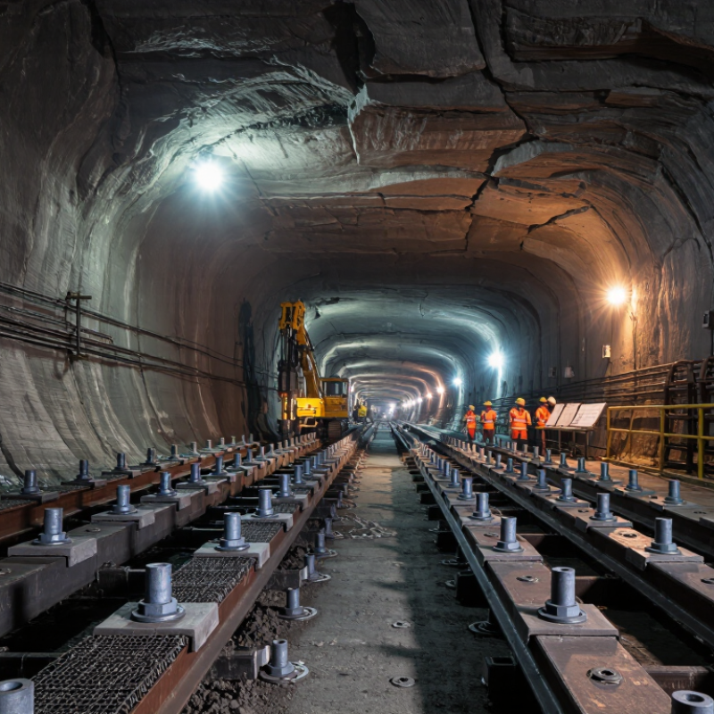
Roof bolt spacing in Rock Mass Rating systems is not a fixed number. RMR describes rock quality, while spacing translates that quality into a practical support pattern. Higher RMR values often permit wider spacing, but the relationship is not automatic.
RMR considers intact rock strength, rock quality designation, discontinuity spacing, groundwater, and joint orientation. A roof with moderate RMR may still need close bolts if joints form loose blocks above the excavation. In Chinese underground projects, engineers may begin with a regular grid near 1.0 to 1.5 meters, then adjust it after mapping and monitoring. This range is only a starting point.
Site evidence matters most. Check exposed joints, bolt pull-test results, convergence readings, and signs of fresh cracking. A clean grid can still fail when bolts miss weak planes or plates do not seat firmly. Shorter spacing may improve confinement, but excessive bolts can slow installation and hide poor geological judgment. That is an uncomfortable limitation. RMR is useful, but it simplifies a changing rock mass. I would review spacing after each excavation advance, especially near faults, water-bearing seams, or sharply inclined joints. Experienced supervision should confirm the final pattern through approved calculations, field observations, and documented monitoring.
What Roof Bolting Spacing Means in Rock Mass Rating Systems
This chart summarizes representative upper-limit bolt spacing values commonly associated with RMR-based underground support guidance. Higher RMR values indicate better rock quality and may allow wider or localized bolting, while lower RMR values generally require closer, systematic reinforcement. Actual spacing must be verified through site investigation, excavation geometry, stress conditions, groundwater, bolt capacity, and local engineering standards.
Rock Mass Rating classes provide a useful starting point for roof bolt spacing. They do not replace site-specific ground control design. Bieniawski’s RMR system divides rock masses into five classes, from very good rock at 81–100 to very poor rock below 20. In good rock, engineers may consider wider spacing, often around 1.5–2.0 metres. Fair rock commonly requires systematic bolts near 1.2–1.5 metres apart. Poor rock may need closer spacing, mesh, and surface support.
These ranges reflect guidance in Bieniawski’s Engineering Rock Mass Classifications and the Norwegian Geotechnical Institute’s Q-system support recommendations. However, RMR classes influence more than bolt distance. They also affect bolt length, anchorage, face plates, mesh coverage, and shotcrete requirements. A 1.5-metre pattern can perform well in stable, blocky ground. The same pattern may fail where joints daylight into the excavation.
Field engineers should verify the rating through fresh mapping, borehole observations, and routine convergence checks. Water inflow, high stress, blasting damage, and roof span can reduce the practical value of an otherwise favorable RMR score. Published guidance is useful, but local measurements matter more. I have seen neat theoretical patterns become questionable after one wet fracture zone appeared. That detail deserves attention.
For preliminary design, RMR 61–80 may support wider, selective bolting. RMR 41–60 usually favors systematic reinforcement. RMR below 40 demands conservative spacing and stronger surface control. Final spacing should follow approved calculations, monitoring results, and competent ground-control review.
China Best Roof Bolting Spacing for Rock Mass Rating?
Selecting roof bolt spacing starts with a reliable RMR assessment. Record uniaxial compressive strength, RQD, joint spacing, joint condition, and groundwater. Bieniawski’s 1989 RMR support table gives useful baseline data for approximately 10-metre tunnel spans. For RMR 61–80, it suggests about 2.5-metre bolt spacing. RMR 41–60 reduces spacing to 1.5–2 metres. RMR 21–40 commonly requires 1–1.5 metres, with mesh and longer bolts. These values are starting points, not final designs.
Adjust the spacing step by step. Check the roof span, bed thickness, joint direction, excavation method, and expected vibration. A weak horizontal bedding plane may need closer bolts than its RMR score suggests. Review bolt length and anchorage, not spacing alone. Field pull tests, installation records, and convergence readings should confirm the design. Guidance from international rock-engineering practice stresses observational control because geological conditions change quickly. The first estimate is often wrong.
Tips: Keep a roof map at the working face. Mark every joint set and wet zone. Reduce spacing near intersections, faults, and brows. Inspect plates for bending or fresh cracking. If monitoring shows increasing displacement, stop treating RMR as a fixed answer. Recalculate the rock class and revise the support pattern. NIOSH ground-control guidance also emphasizes systematic installation checks, because a perfect spacing plan cannot compensate for poor anchorage or incomplete tightening.
China Best Roof Bolting Spacing for Rock Mass Rating?
Site Conditions That Require Adjustments to Standard Spacing
RMR guidelines often suggest 1.5–2.0 metre bolt spacing for fair rock. Bieniawski’s 1989 support tables provide useful starting ranges, not fixed prescriptions. A 2.0 metre grid may perform well in massive rock. It can fail beside a clay-filled joint or a faulted roof beam.
Groundwater demands closer attention. Seepage can soften infill and reduce bolt anchorage. In fractured zones, spacing may need reduction to 1.0–1.5 metres. Joint orientation matters too. Discontinuities dipping toward the excavation require bolts that cross the likely sliding direction. Wide intersections, sudden roof changes, and blast-damaged surfaces also deserve tighter patterns. FHWA-NHI-10-034 stresses that rock structure, groundwater, stress, and excavation geometry must influence support design. RMR alone cannot capture every local hazard.
Tips: Map joints within each roof-bolt cycle, not only during the initial survey. Check hole return, resin or grout performance, and plate contact. Use pull tests and convergence readings to confirm the pattern. A neat grid can still be wrong. I would rather adjust spacing after measured movement than defend an attractive drawing. Leave additional capacity near brows, intersections, and geological contacts. Review unsupported exposure time as well; weak ground may deteriorate before installation begins.
| RMR Range | Rock-Mass Class | Typical Roof Condition | Indicative Initial Bolt Spacing | Typical Bolt Length | Recommended Support Pattern | Conditions Requiring Closer Spacing | Practical Adjustment |
|---|---|---|---|---|---|---|---|
| 81–100 | Very good rock | Strong, slightly jointed rock with stable blocks and limited weathering. | Usually no systematic bolting; local support may be required. Where bolts are installed, approximately 2.0–2.5 m grid spacing may be used as a preliminary control measure. | Approximately 2.0–3.0 m, subject to roof geometry and anchorage quality. | Spot bolts at loose blocks, intersections, brows, faults, and local wedges. | Adverse joint orientation, high exposed span, blasting damage, water inflow, or signs of block movement. | Reduce spacing to about 1.5–2.0 m in affected areas and add mesh or straps where loose pieces can fall. |
| 61–80 | Good rock | Competent rock with several joint sets but generally stable excavation surfaces. | Approximately 1.5–2.5 m in a systematic pattern. | Approximately 2.4–3.5 m. | Systematic roof bolts; add mesh or straps where joints form small wedges. | Persistent joints parallel to the excavation, open joints, thinly bedded rock, wet seams, or larger-than-normal excavation spans. | Use approximately 1.2–1.8 m spacing locally; consider longer bolts, straps, mesh, or additional cable support for large blocks. |
| 41–60 | Fair rock | Moderately fractured or blocky rock with possible wedge formation and localized ravelling. | Approximately 1.2–1.8 m systematic spacing. | Approximately 3.0–4.0 m, or long enough to develop anchorage beyond the loosened zone. | Systematic bolts with mesh and bearing plates; straps may be needed across bedded or blocky ground. | High joint frequency, clay-filled discontinuities, water pressure, damaged excavation perimeter, or stress-induced spalling. | Tighten spacing to approximately 0.9–1.5 m; increase bolt length and add steel sets, shotcrete, or cable bolts when deformation continues. |
| 21–40 | Poor rock | Highly fractured, closely jointed, weathered, or weak rock with frequent ravelling and unstable blocks. | Approximately 0.9–1.5 m systematic spacing. | Approximately 3.5–5.0 m, depending on the thickness of the loosened zone. | 密集 systematic bolts with fully covered mesh, straps, and a surface support layer where required. | Running ground, weak seams, squeezing behavior, significant groundwater, overbreak, or unsupported spans exceeding the design basis. | Use approximately 0.6–1.2 m spacing; install support rapidly after excavation and consider forepoling, spiling, shotcrete, steel sets, or cable bolts. |
| <21 | Very poor to extremely poor rock | Crushed, highly weathered, faulted, swelling, squeezing, or running ground with limited self-support capacity. | Approximately 0.6–1.2 m only as an initial guide; spacing must be confirmed by site measurements and ground-response observations. | Approximately 4.0–6.0 m or more, subject to stable anchorage and the required reinforcement zone. | 密集 bolts with mesh, straps, shotcrete, yielding or steel support, and advance support where necessary. | Collapse-prone ground, major faults, high convergence, swelling clay, bursting or squeezing, heavy water inflow, and inadequate anchorage. | Do not rely on bolt spacing alone; shorten excavation advances, reduce spacing as needed, and use combined support designed by a qualified geotechnical engineer. |
RMR provides a useful starting point, not a final spacing answer. At a Chinese underground site, inspectors should compare the design with exposed roof conditions. Record joint spacing, groundwater, bedding direction, and loose fragments. A neat bolt grid can still perform poorly. Local weak bands may require closer support than the general RMR category suggests. Experienced geotechnical engineers should review these differences before approving changes.
Field verification must examine more than bolt presence. Check plate contact, bearing damage, resin mixing, bolt inclination, and installation records. Measure roof convergence at fixed stations. Repeat readings after blasting, heavy rainfall, or visible cracking. Pull tests and torque checks should follow approved procedures and qualified supervision. Borehole inspection can reveal separation above the visible roof. It often exposes problems that routine visual checks miss.
Spacing should be adjusted only through documented engineering review. An isolated failed bolt does not automatically prove the whole pattern is unsafe. However, repeated plate distortion or increasing convergence demands prompt reassessment. One practical weakness is relying on clean inspection areas. Dust, water, and poor lighting can hide early damage. Inspectors should photograph defects with scale references and record exact locations. Field notes must include uncertainties, because incomplete data can make a confident decision unreliable.
RMR classifies rock quality from very good to very poor. It helps engineers choose an initial roof-bolt pattern. It is not a final design.
Very good rock may allow wider spacing, often about 1.5–2.0 metres. Wider spacing still requires stable joints and suitable roof geometry. Check the roof.
Fair rock often needs systematic bolts about 1.2–1.5 metres apart. The pattern may require mesh or surface support. Conditions can change quickly.
Poor rock usually needs closer bolts, shorter unsupported exposure, and stronger surface control. Mesh and shotcrete may also be necessary. Conservative planning helps.
It may fail near a fault, clay-filled joint, or damaged roof beam. Reduce spacing when fractures are open, weak, or unfavorably oriented. A neat grid can still be wrong.
Water can soften joint infill and reduce anchorage quality. Fractured wet zones may require spacing near 1.0–1.5 metres. Watch seepage after installation.
Bolts should cross the likely sliding direction of unstable blocks. Joints dipping toward the excavation can create sliding hazards. Mapping each bolt cycle reveals changes.
Check borehole returns, resin or grout performance, and plate contact. Use pull tests and convergence readings. Measurements may challenge the original drawing.
High stress, blasting damage, roof span, water inflow, and changing geology can weaken the design basis. RMR alone misses local details. That matters.
Review spacing after fresh mapping, unexpected movement, water entry, or a new fracture zone. Add capacity near intersections, brows, and geological contacts. Waiting may cost stability.
Roof bolting spacing is a key part of safe and effective ground control in mining, and it should be selected according to the rock mass rating (RMR) of the surrounding strata. How does rock mass rating affect mine roof bolting spacing? In general, stronger and more stable rock may permit wider bolt spacing, while weaker, fractured, or highly weathered rock usually requires closer spacing, stronger reinforcement, or additional surface support. RMR classes provide a practical framework for comparing roof conditions and establishing an initial support pattern.
A reliable selection process includes evaluating the RMR class, reviewing roof thickness and geological structures, choosing a preliminary bolt grid, and checking the design against load, deformation, and operational requirements. Standard spacing must be adjusted where faults, joints, water, stress concentrations, weak layers, or changing excavation geometry are present. Regular field inspections are essential for verifying bolt installation, observing roof movement, identifying damaged areas, and confirming that the support system performs as intended.-vesm
