How to Prevent Roof Bolter Failure in Soft Rock 2026?

Time:2026-10-14 Author:Ethan
0%

Soft rock can turn a reliable roof bolter into a costly safety risk. Weak shale, claystone, and fractured sandstone often collapse around the drill steel. Water may soften the roof further. Poor flushing can also pack cuttings inside the hole. These conditions reduce drilling accuracy, bolt anchorage, and installation speed.

What are the common causes of roof bolter failure in soft rock? The answer usually involves several connected problems. Excessive feed pressure can bend the drill steel or overload the boom. Incorrect rotation speed may polish the hole instead of cutting it. Mud-filled holes can prevent resin cartridges from bonding correctly. Worn bits, blocked water lines, damaged hoses, and neglected hydraulic filters create additional stress. Operators should inspect torque, vibration, oil temperature, and unusual sounds during every shift. Small changes matter.

Ground-control specialist Dr. Christopher Mark offers a practical principle: “Support must match the ground, not the plan.” That idea should guide every prevention strategy. Mine teams need site-specific drilling trials, updated roof classifications, and clear maintenance records. They should test bolt pull resistance when conditions change. A simple note about softer strata can prevent repeated equipment damage. No checklist is perfect. Human judgment still matters. Sometimes, crews focus heavily on production and miss early warning signs, such as slower penetration or sudden water loss. Better training, honest reporting, and conservative decisions can protect both the roof bolter and the people working beneath it.
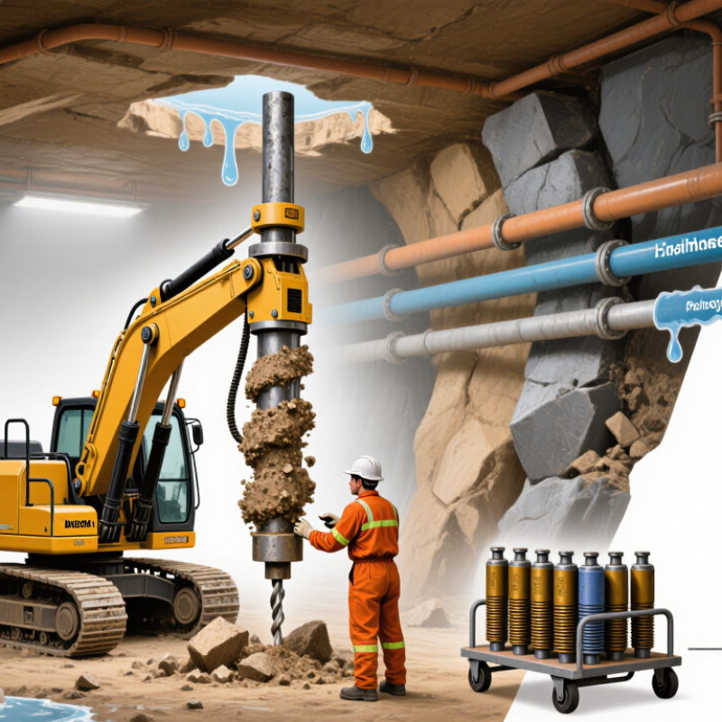
How to Prevent Roof Bolter Failure in Soft Rock 2026?

Understanding Soft-Rock Conditions and Roof Bolter Failure Risks

Soft rock can look stable at the start of a shift, then deform within minutes. Weak shale, clay bands, moisture, and fractured bedding can reduce roof strength quickly. These conditions increase roof bolter failure risks, including bit clogging, hole collapse, hydraulic overload, and unstable equipment positioning.

A competent ground assessment should guide every bolting plan. Inspect exposed strata for slabbing, dripping water, fresh cracks, and unusual convergence. Check drilling resistance as the bit enters each layer. Sudden resistance changes may indicate clay seams or broken rock. Use suitable drilling pressure and rotation speed. Excessive force can bend rods, damage threads, or overload the feed system. Keep the machine level, and never ignore uneven floor conditions.

Small details matter.

In practice, crews should record hole depth, drilling time, torque changes, and failed components. These records help maintenance teams identify repeated patterns instead of replacing parts blindly. Regular inspection of hoses, couplings, guards, and emergency controls also reduces avoidable failures. However, no checklist catches everything. A dry roof may still hide a weak bedding plane, and experienced workers can misread changing geology. Geotechnical reviews should be updated after water inflow, blasting changes, or visible roof movement. Stop and reassess when the rock behaves differently. That decision may feel slow, but rushed drilling often creates greater equipment and ground-control risks.

Selecting the Right Roof Bolter for Weak and Unstable Ground

How to Prevent Roof Bolter Failure in Soft Rock 2026?

Selecting the right roof bolter for weak ground starts with the rock mass, not the machine catalogue. Review core logs, fracture spacing, groundwater, clay content, and roof convergence before choosing equipment. Soft shale may collapse around a hole within minutes. Wet clay can also seize drill steels and reduce penetration control.

Choose a bolter with precise feed control, stable tramming, and enough torque for variable resistance. Excessive thrust can crush weak strata and create oversized holes. Low thrust may leave anchors poorly seated. A compact machine with a protected operator canopy can improve control in narrow entries. Check whether the boom reaches the planned bolt pattern without forcing the machine against uneven floor.

Use drilling trials at several roof locations. Measure penetration time, water return, hole diameter, and bolt installation torque. These details expose problems that specifications often miss. In practice, a slightly slower machine may perform better when its controls remain smooth. Dust and water protection also matter because sensors, hoses, and hydraulic fittings face constant abuse.

No selection chart is perfect. I have seen crews trust a strong-looking machine that struggled when the roof became wet. That mistake deserves review. Match the bolter to local geology, planned bolt length, resin or grout method, and maintenance capacity. Train operators to stop when the roof changes, rather than forcing the same settings through every cut. Thin steel plates, damaged hoses, or inconsistent torque readings should trigger inspection before the next cycle.

How to Prevent Roof Bolter Failure in Soft Rock 2026?

Selecting the right roof bolter for weak and unstable ground starts with understanding the rock mass strength. The chart shows commonly used ISRM uniaxial compressive strength (UCS) ranges for soft to medium-strong rock.

Very weak and weak rock requires careful feed-force control, stable drilling alignment, suitable bolt-hole support, and frequent inspection. UCS should be evaluated together with jointing, groundwater, in-situ stress, and roof deformation before choosing drilling and bolting equipment.

Preparing the Work Area Before Drilling and Bolting

How to Prevent Roof Bolter Failure in Soft Rock 2026?

Preparing the work area before drilling and bolting starts with ground control, not machine power. MSHA reported 40 mining fatalities in the United States during 2023, showing that basic preparation still demands attention. A competent supervisor should examine the roof, ribs, and floor before equipment enters. Loose slabs must be scaled from a protected position. Barricades should separate unsupported ground from the work zone. Good lighting matters. Small cracks often disappear in shadow.

Soft rock can deform around the drill collar and reduce hole accuracy. Clear mud, standing water, and loose cuttings before drilling. Check the floor for soft pockets that may shift the bolter’s tracks or stabilizers. Verify ventilation, drainage, communication, and emergency access. The International Society of Rock Mechanics recommends documenting changing ground conditions, while NIOSH ground-control research repeatedly identifies unsupported exposure and poor geological assessment as major risk factors. Record roof height, rock changes, water inflow, and previous bolt performance.

Use a pre-shift checklist, but do not treat it as paperwork. Stop when conditions change. The face may look stable. It may not be. I have seen crews focus on drill speed while ignoring a weakening rib line. That mistake deserves review. Recheck alignment after every machine move, confirm the planned bolt pattern against current conditions, and report failed holes immediately. Small delays are cheaper than correcting a collapsed work area.

Applying Correct Drilling, Bolting, and Ground-Support Procedures

How to Prevent Roof Bolter Failure in Soft Rock 2026?

Soft rock changes quickly after excavation, so roof bolting must begin from a verified ground assessment. Examine exposed strata, water inflow, bedding direction, and signs of slabbing before drilling. Record loose fragments and unexpected voids. Small details matter.

Use sharp, correctly sized drill bits and maintain alignment with the planned bolt pattern. Excessive feed pressure can enlarge holes and damage weak rock. Clean each hole thoroughly before installing the bolt. A blocked hole may prevent proper anchorage. Check resin or grout placement, bolt length, installation torque, and plate contact according to the approved support design.

Ground support should match actual conditions, not only the original drawing. Add mesh, straps, cable bolts, or additional reinforcement when the roof becomes laminated, wet, or highly fractured. Inspect the bolter’s hydraulic hoses, rotation system, torque controls, and emergency functions every shift. Do not ignore unusual vibration. It may indicate worn tooling or unstable ground.

Field experience shows that rushed drilling creates hidden weaknesses. I have also seen support plans remain unchanged after geology shifted. That is a mistake worth revisiting. Supervisors should compare installation records with monitoring data and stop work when measurements exceed site limits. Competent personnel, clear procedures, and documented inspections make support more reliable. Even a well-designed system can fail when installation quality is inconsistent.

How to Prevent Roof Bolter Failure in Soft Rock 2026? - Applying Correct Drilling, Bolting, and Ground-Support Procedures
Practical control matrix for soft-rock roof bolting, equipment reliability, and ground-support quality
Control Area Critical Variable Recommended Practice or Typical Range Failure Risk When Incorrect Verification Method Corrective Action Priority
Ground Assessment Roof condition mapping Inspect bedding, joints, clay bands, moisture, brows, loose slabs, and signs of roof deformation before drilling. Unexpected falls, hole deviation, bolt loss, and damage to the drilling unit. Documented pre-shift inspection, visual scaling, convergence observations, and geological mapping. Stop work beneath unsupported ground and revise the support pattern with the responsible ground-control engineer. Critical
Ground Assessment Unsupported exposure Keep the active unsupported area within the approved roof-control plan; minimize the distance between the face and the first installed support. Progressive ravelling and sudden roof falls before support can be installed. Measure the exposed distance after each cut and compare it with the approved plan. Reduce cut depth, install temporary support, or change the mining sequence when the limit is exceeded. Critical
Drilling Hole diameter and bit condition Use the hole diameter specified for the selected bolt and resin or grout system. Replace worn, damaged, or blunt bits promptly. Poor anchorage, excessive installation torque, bolt spinning, and premature drill-component wear. Measure sample hole diameters and inspect bit wear at defined intervals. Correct the bit size, replace worn tooling, and clean blocked flushing passages. High
Drilling Drilling alignment Maintain the planned angle and collar position; use guides or templates where bedding planes make hole deviation likely. Reduced anchorage length, plate loading problems, bolt bending, and ineffective reinforcement. Check hole angle with a drill guide, alignment gauge, or approved survey method. Re-drill nonconforming holes only after confirming that the surrounding ground remains safe. High
Drilling Flushing and hole cleanliness Flush cuttings continuously and remove loose material before resin, grout, or mechanical anchorage is installed. Voids, incomplete encapsulation, poor resin mixing, and loss of bond strength. Check return flow, observe cuttings discharge, and inspect representative holes before installation. Restore water or air flushing, clean the hole, and do not install support in a blocked hole. High
Drilling Feed force and rotation control Use steady feed and rotation settings appropriate to the rock strength; avoid excessive thrust that stalls the drill or fractures the collar. Hydraulic overheating, rod bending, bit damage, hole deviation, and unstable collars. Review operating readings, drill sound, penetration behavior, and hose temperature. Reduce feed force, check hydraulic settings, sharpen or replace tooling, and inspect the drill string. High
Bolting Support spacing and pattern Follow the approved ground-control plan. Typical patterns may use approximately 1.0–1.5 m spacing, but the design must reflect geology, span, and loading. Insufficient reinforcement, excessive roof movement, and localized overload of individual bolts. Measure bolt rows, spacing, edge distance, and installation coverage. Increase support density or install supplemental support when mapping identifies weak bands, intersections, or wider spans. Critical
Bolting Embedment and bolt length Use the length and anchorage arrangement specified by the design. The bolt must extend through the unstable layer and develop anchorage in competent material where required. Anchorage failure, pull-through, plate separation, and inadequate beam formation. Record drilled depth, bolt length, and installed depth; perform approved proof or pull testing. Replace short or shallow installations and reassess the support design if competent anchorage is unavailable. Critical
Bolting Resin or grout installation Use products within their storage life and temperature limits. Ensure correct cartridge placement, mixing, spin time, and hold time according to the system instructions. Incomplete mixing, low bond strength, uncured anchorage, and bolt spin-out. Check batch information, installation time, cartridge condition, and sample pull-test results. Quarantine suspect materials, correct installation timing, and re-support failed locations. Critical
Bolting Plate seating and tension Seat the plate firmly against sound rock or the specified surface; apply the designed torque or tension without crushing weak rock. Loss of surface restraint, plate punching, bolt overstress, or inadequate confinement. Visual inspection, torque or tension measurement, and checks for plate rocking or gap formation. Install larger or approved bearing plates, add mesh or straps, and retension only when permitted by the support design. High
Surface Support Mesh, straps, and screen contact Install surface support tightly against the roof with adequate overlap and secure attachment between adjacent bolts. Ravelling between bolts, falling slabs, mesh sag, and unconfined loose material. Inspect overlap, fasteners, contact, tears, and unsupported gaps during every shift. Repair damaged mesh, close gaps, add straps, and install supplemental bolts where required. High
Equipment Reliability Hydraulic system condition Maintain clean fluid, correct pressure, sound hoses, functioning relief valves, and leak-free fittings. Loss of drilling force, overheating, uncontrolled movement, and premature pump or motor failure. Daily leak inspection, pressure checks, temperature monitoring, and scheduled fluid sampling. Isolate leaks, replace damaged hoses, clean or replace filtration, and investigate repeated pressure loss. Critical
Equipment Reliability Drill steel, chuck, and rotation head Inspect rods, threads, couplings, chuck jaws, rotation head, and feed components before each shift. Rod breakage, stuck steel, hole deviation, vibration, and unplanned downtime. Use a documented inspection checklist and trend defects by operating hours. Remove bent or cracked components from service and correct misalignment before continued drilling. High
Equipment Reliability Dust and water management Use effective wet drilling or approved dust-control methods while preventing water accumulation in weak, moisture-sensitive ground. Respiratory exposure, blocked holes, corrosion, slippery work areas, and softening of clay-rich roof. Check dust suppression, drainage, visibility, and water pooling at the work area. Improve drainage and suppression controls; stop drilling if visibility or ground stability is compromised. Critical
Quality Control Installation records Record location, bolt type, length, hole depth, installation time, resin or grout batch, defects, and corrective work. Repeated failures remain hidden and support performance cannot be traced. Compare shift records with inspection results, ground conditions, and maintenance data. Use trend analysis to identify recurring failure modes and update procedures or training. High
Verification Proof and pull testing Test representative installations and any suspect support in accordance with the approved site procedure and applicable regulations. Undetected low-capacity bolts remain in service beneath active work areas. Use calibrated test equipment and record load, displacement, location, and acceptance result. Isolate failed support, investigate the cause, install replacement support, and expand testing when a trend is detected. Critical
Monitoring Roof movement and convergence Monitor deformation at intersections, faults, wet zones, wide spans, and locations with repeated support damage. Progressive failure is not identified until significant damage or collapse occurs. Use visual inspections, tell-tales, convergence measurements, extensometers, or approved monitoring systems. Increase inspection frequency, restrict access, and install additional support when movement exceeds trigger levels. Critical
People and Procedure Operator competency Train operators in ground recognition, drill control, bolt installation, equipment limits, emergency response, and defect reporting. Incorrect settings, unsafe positioning, poor installation quality, and delayed escalation. Use competency assessments, task observations, refresher training, and pre-start briefings. Stop unauthorized work, provide coaching, and reassess competency before the task resumes. Critical
Emergency Control Response to unusual ground behavior Withdraw personnel when cracking, audible loading, sudden water inflow, roof sag, falling fragments, or abnormal machine vibration is observed. Exposure to an active ground failure or uncontrolled equipment event. Confirm that the withdrawal and re-entry procedure is understood and practiced. Establish an exclusion zone, notify supervision, reassess the ground, and re-enter only after authorization. Critical
Note: The ranges and practices shown are typical engineering control values for planning and quality review. Final bolt type, length, spacing, installation parameters, testing frequency, and trigger levels must be determined by the site-specific ground-control plan, geological conditions, equipment limits, applicable regulations, and a qualified ground-control professional.

Inspecting, Maintaining, and Improving Roof Bolter Performance

Soft rock can make roof bolters fail without much warning. Loose strata, water, and abrasive dust increase stress on the feed system, drill head, and hydraulic lines. A practical inspection should begin before each shift. Check hose abrasion, fluid leaks, damaged guards, loose fasteners, and unusual movement in the boom. Examine drill bits and sleeves for uneven wear. These small clues often appear before major downtime.

Maintenance records should describe symptoms, not only replaced parts. Note feed pressure, rotation speed, drilling time, and the location of repeated problems. Compare these records across shifts. A sudden rise in drilling resistance may indicate changing ground conditions or a worn component. Clean air and hydraulic filters at the recommended intervals. Contaminated fluid can damage valves and reduce control accuracy. Never ignore a minor leak. It can become a serious failure underground.

Performance improves when operators adjust technique to the rock. Excessive feed pressure can bind the drill steel and damage the rotation unit. In soft, wet ground, slower penetration and steady alignment usually provide better control. Ground support settings should follow the approved site plan and qualified engineering guidance. Short toolbox discussions help operators share changes they have noticed. Still, inspections are not perfect. A hidden crack or missed hose rub can escape a busy checklist. Reviewing failures honestly, then updating the checklist, makes the next inspection more useful.

FAQS

How should a roof bolter be selected for weak and unstable ground?

Start with the rock mass, not the equipment catalogue. Review fractures, groundwater, clay content, and roof movement. Soft shale may collapse within minutes.

Which machine features matter most in soft rock?

Choose precise feed control, stable movement, and sufficient torque. Excessive thrust can crush weak strata. Low thrust may leave anchors poorly seated.

Can a compact roof bolter improve underground control?

Yes, especially in narrow entries. A protected canopy supports safer operation. The boom should reach the bolt pattern without pushing against uneven flooring.

What should drilling trials measure before equipment selection?

Test several roof locations. Measure penetration time, water return, hole diameter, and installation torque. Specifications can miss these practical details.

How can operators reduce drilling problems in weak ground?

Use sharp, correctly sized bits and maintain alignment. Control feed pressure carefully. Clean every hole before installing an anchor. Blocked holes can weaken anchorage.

When should the ground-support plan be changed?

Change it when the roof becomes wet, laminated, fractured, or visibly unstable. Consider mesh, straps, longer anchors, or added reinforcement. Original drawings are not always enough.

Which warning signs require immediate inspection?

Unusual vibration, damaged hoses, thin plates, and inconsistent torque readings need attention. Loose fragments and unexpected voids also matter. Stop when conditions change.

How can maintenance and records prevent roof bolter failure?

Inspect hydraulic hoses, rotation parts, torque controls, and emergency functions every shift. Compare installation records with monitoring data. I have seen rushed work hide serious weaknesses.

Should operators use the same settings in every excavation area?

No. Wet clay, soft shale, and fractured layers behave differently. Operators should stop and reassess instead of forcing unchanged settings. This simple habit is sometimes neglected.

Is a slower roof bolter always less effective?

Not necessarily. Smooth control may outperform higher speed in weak ground. I once trusted a powerful-looking machine that struggled after the roof became wet. That choice deserved review.

Conclusion

Preventing roof bolter failure in soft rock begins with understanding the ground conditions that create instability, excessive vibration, water damage, and poor anchorage. What are the common causes of roof bolter failure in soft rock? Typical causes include selecting equipment that is unsuitable for weak formations, operating with incorrect drilling pressure or feed speed, inadequate roof inspection, blocked or worn drilling components, and failure to control loose or fractured material. Before work begins, the area should be examined for hazards, properly supported, and cleared of unnecessary obstacles. Operators should choose a roof bolter with suitable power, reach, mobility, and control features for the site.

Reliable performance also depends on consistent drilling and bolting procedures. Correct hole alignment, depth, resin or anchoring placement, and installation pressure help create effective ground support. Regular inspections, cleaning, lubrication, component replacement, and performance monitoring can identify problems early. Training operators to recognize changing rock conditions and respond safely further reduces downtime, improves support quality, and extends the service life of the roof bolter.

Ethan

Ethan

Ethan is a seasoned marketing professional with a deep expertise in our company's innovative product line. With a passion for sharing knowledge and insights, he takes the lead in regularly updating our corporate blog, where he explores industry trends, product features, and effective marketing......